
Our Products
All our products are a PLC Programming Training Course or training collateral that supports a PLC Programming Training Course.
Each PLC Programming Course provides you with:
- Lectures on the concepts of programmable logic controllers,
- Hands-on lab projects that demonstrate the concepts delivered in those lectures,
- And discussions on those hands-on lab projects.
The lectures and discussions are recorded and currently provided as playlists on YouTube on the “plcprofessor” channel. Other than suffering an occasional commercial and the loss of a few moments of your time, they are currently FREE. There is no guarantee that the YouTube format will be there forever or that it will remain free, but we have no intentions otherwise. FREE means FREE!!!
The Hands-on Lab Project manuals are offered on our website as hardcopies only. We do not offer any electronic versions of our manuals. Other than one manual that provides hands-on projects on Ignition SCADA software, they are available for the three current hardware platforms supported by Rockwell Automation (Allen Bradley).
We offer training on three hardware platforms:
- SLC500 & MicroLogix controllers with RSLogix500/MicroStarter
- Control/Compact/FlexLogix/SoftLogix with RSLogix/Studio5000 Logix Designer
- Micro800 controllers with Connected Components Workbench
We label the courses according to the software that provides the programming environment.
PLC Programming Training Course – RSLogix500/Micro Starter
This is the best starting place to learn about PLCs and Ladder Logic Diagrams. It is the simplest, least expensive and most prolific platform available. There will be no new revisions, firmware upgrades for this product. It is fully mature and supported.
Software – We do not sell software
The relationship between the two hardware platforms illustrated below and the programming environment for them is very simple. You must acquire a license for one of these software products listed below to complete this course.
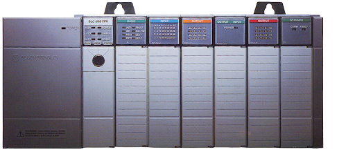
SLC500
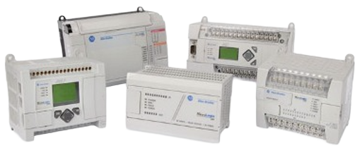
MicroLogi x
Software Licenses
A license for using RSLogix500 provides the platform to program and troubleshoot all SLC500 processors and all MicroLogix processors, with the support for online editing cost “standard edition” cost between $2600.00 and $3600.00.
A license for using the stripped-down version of RSLogix500 offered as Micro Starter and provides a software platform to program and troubleshoot all MicroLogix processors/controllers cost between $180.00 and $224.00, the difference being electronic download and physical media. “Recommended Choice”. This license is acquired directly from a Rockwell Automation distributor…ONLY!
A license for using the FREE stripped-down version of RSLogix500 offered as Micro Starter Lite and provides a software platform to program and troubleshoot MicroLogix1000 and MicroLogix1100 processors/controllers cost $0.00. This license does not support online edits. You must save, go offline, make your edits, save, download and go back to the online Run mode.
To acquire the free software from Rockwell Automation:
- Create a free account on RA website,
- Login, Search for Micro Starter Lite, select latest version and download.
- Install the software onto your computer, RSLinx, MicroStarterLite and Emulate500.
An option, but not free. We offer a USB memory stick with the three apps listed above in step #3. You can order volume one of the set of manuals with that USB memory stick as a variant. You are purchasing the memory, stick and the labor to find and load the files onto that device. I include other valuable files to fill out the plate.
PLC5
The relationship between earlier Allen Bradley platforms, programming software and their current supported hardware platforms in relationship to this course.
The software license to program and troubleshoot PLC5 hardware can run from $3,500.00 annually to $19,825.00 for a perpetual license.
This course does not demonstrate the use of this platform but RSLogix is RSLogix. If you complete this PLC Programming Training Course with a SLC500 or MicroLogix, you will find yourself at home using RSLogix5 with the PLC5 platform. The major differences between SLC500/MicroLogix is in the I/O structure and communication (Block Transfers).
Hardware – We do sell some hardware
We do not recommend SLC500 as a hardware platform for completing this PLC Programming Training Course. If you already have access to SLC hardware and RSLogix500 that supports that hardware, then take advantage of that which is hand. Otherwise, you will use the FREE 500 Emulate or a MicroLogix controller.
All these controllers have multiple I/O and Power configurations. Ideally you want a controller that requires 24vdc for power and NOT 115vac which is a shock hazard. You also want an I/O configuration that provides maximum flexibility. The ideal choice is 100% DC inputs, DC outputs and 24vdc power requirements. The second best choice would have relay outputs instead of DC outputs…there is no third best choice!!!
RSEmulate500
You can use 500 Emulate with the Free version of MicroStarter Lite that you either downloaded from Rockwell Automation or came free on the USB Memory stick that you purchased from us as a variant.
Using 500 Emulate…Click on this link…
MicroLogix1000
The MicroLogix1000 platform has been discontinued by Rockwell Automation but is 100% compatible with the software and is more than sufficient to complete this course with. HOWEVER…it does not support online programming and the current prices for this discontinued processor does not make it an ideal choice for this PLC Programming Training Course.
MicroLogix1100
This platform does support online programming…AND IT Has an ETHERNET port and you can program it with the free version of software…but the free version of software does not support online editing. A better choice than a MicroLogi1000 but the price of these units ($450-$800) online is prohibitive to your total investment in this course.
MicroLogix1200/1500
You can use one of these to complete the course and they are inexpensive…BUT…they do not support online editing, you cannot use the free software and they do not have an ethernet port. They would be the worst choice.
MicroLogix1400 – Recommended
The MicroLogix controllers were introduced in this order, ML1000 – ML1200 – ML1500 followed by the ML1100 and finally the MicroLogix1400.
Any MicroLogix1400 that does not use 115vac is a good choice for this course. There are two primary models…digital I/O only or with analog inputs and outputs. However, we recommend the 1766-L32BXB or 1766-L32BXBA, digital I/O only or digital and analog I/O. If you can afford to invest a little more, I would pick the BXBA and it does not eliminate anything that the BXB has, it just adds analog inputs and outputs.
Hands-on Lab Project manuals
This PLC Programming Training Course requires this two-volume set of hands-on lab project manuals. Just short of 500 pages of full-colored, high-quality printing with step-by-step instructions.
Click on this link to view the table of contents and page examples for the first volume.
Click on this link to view the table of contents and page examples for the second volume.
The 247 pages of content in the first volume of the PLC Programming Training Course for RSLogix500 and MicroStarter coverage includes:
Basic Ladder Logic Diagrams – Boolean
- The five original instructions are based on the wiring symbols and function of a standard relay and the latching relay, XIC, XIO, OTE for the standard relay functions; OTL and OTU for the unique functions of a latching relay. These five instructions are analogous, respectively, to TrueIfON, TrueIfOFF, Energize the Coil for the standard relay function and Latch the Coil On and Unlatch the Coil for the latching relay functions.
Basic Ladder Logic Diagrams – Timing and Event Detection
- After the basic functions of hardwired electromagnetic relays were developed in Ladder Logic Diagrams, hardwired timers and counters were adapted into Ladder Logic Diagrams. The original timers found in relay panels provided the engineer with the options of delaying the energizing (TON) of a device or delaying the de-energizing (TOF) of a device and triggering the reset (RES) of the timing period. An additional option was to accumulate smaller delays to reach a larger preset (RTO).
- The hardwired counters in relay panels used a ratcheting wheel to display the count of events that energized the solenoid that drove the ratchet. The (CTU) instruction increments an integer to the same purpose and the (CTD) reverses the integer or decrements the value The same reset instruction (RES) used with timers is used to reset a count to zero.
- These 11 instructions replaced the electromechanical functions in a relay panel with microprocessor functions to give the engineer basic programming for ladder logic diagrams.
Beyond the original Ladder Logic Functions
Comparison Instructions:
- Greater Than (GRT), Less Than (LES), Greater Than or Equal (GEQ), Less Than or Equal (LEQ), Equal (EQU), Not Equal (NEQ), Masked Equal (MEQ) and Limit (LIM).
Basic Math Instructions:
- Add (ADD), Subtract (SUB), Multiply (MUL) and Divide (DIV).
Data Manipulation:
- Move or word copy (MOV) and Move or word copy with a mask (MVM)
- Shift Registers – Bit shift right (BSR) and Bit shift left (BSL).
Boolean Algebra – An introduction
Supporting hardware for the PLC Programming Training Course
Digital Field Device Simulator
A digital field device simulator simulates digital input field devices like photo eyes, limit switches, pushbuttons etc.… by connecting switches to the terminals of your controller that you can switch on or off to exercise your programs while you are learning. It also simulates digital output field devices like contactors, motor starters and solenoids by connecting LED indicators to the output terminals of your controller
This is the learning station that we use in our on-site PLC Programming Training Course. The gray box with 6 inputs and 6 outputs is our Digital Field Device Simulator. We offer just the parts as a kit…with instructions.
Click here for instructions to assemble the kit.
Click here for instructions to build your own version. This is an older video and one using hobbyist parts to build a digital field device simulator. Warning…it is old…
Lectures – YouTube
Click here for the playlists of lectures for this course.
Summary:
You do not have to purchase anything to use most of our training materials. The lectures are free, the software is free and you can provide your own projects instead of purchasing our project manuals. The free software includes RSEmulate 500 to simulate a controller, not easy to use…but it is FREE!
The optimum choices include Microstarter purchased from the distributor, the set of manuals shown above, a Micrologix1400 1766-L32BXB. Either way the lectures are free on YouTube.